With the insights from part 1 it is clear that we need a circuit which can produce the modulated signal:
After some searching and consideration I found the AD633 from Analog Devices which is an analogue multiplier with differential inputs which does the following:
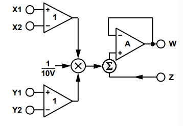
From the figure one can see that it basically performs the following operation (i.e. transfer function):
In our case we have and . Also, we reuse the carrier as Z, i.e. . We then get:
Factor out the carrier:
Finally, replace with a new modulation index, , and we get:
We have now arrived at exactly the general form for the modulated signal for DSB-LC AM as discussed before in part 1.
This is very nice and I therefore intend to use the AD633 as the core component in my transmitter.
Generally, I need to find a good way to generate the carrier and choose a signal source for the audio. I have previously used AD9833 for signal generation and since I am familiar with it I will use it again and control it via an Arduino. The design I then have in mind is to use a dual OP, e.g TL072CP, to handle the two inputs and to be able to easily adjust e.g. modulation index. There are several other nice advantages with using OPs so that is probably a solid choice. At the other end of the AD633 things are still a bit more vague. Hopefully, there will be a nice AM signal at the output if everything works out as expected.
I then plan to feed the signal into an amplifier which will probably consist of essentially a couple of transistors. It also crucial to ensure that no harmonics (overtones) exist at the output (at least they should be sufficiently small). I’ll see what components I have in stock, but I think need a general component refill anyway so it is now time to buy everything needed to be able to actually build something.
At the far end of this project it is also worth noting that there will be a tuning problem when connecting the transmitter to an antenna since the dimensions of a matching antenna will be overwhelming due to the wavelengths are very long, hence the name Long Wave. For a frequency of e.g. 200 kHz the wavelength is 1.5 km.
To be continued…